PD1500A System Calibration Including Probe Compensation, Deskew, and Shunt De-Embedding
Introduction to PD1500A Si/SiC Calibration
Several calibration-related procedures should be performed regularly: anytime the DUT modules or Gate Drive Modules are changed, anytime the ambient temperature changes ±5 °C, or anytime oscilloscope probes are changed.
- Oscilloscope Probe Compensation
- System Calibration
- Oscilloscope Probe Deskew
- Coaxial Shunt Resistor Calibration & De-embedding. Calibration should be performed annually. A De-embedding file will be available for Keysight InfoLine and should be installed in the oscilloscope immediately after calibration. See Obtain and Install Coaxial Shunt Resistor De-Embedding File” on in the PD1500A Service Guide or the PD1500A Software Guide.
Additionally, a Full Calibration (also known as Service Calibration) is required annually for the DSOS104 or MXR108 oscilloscope, 33512B Waveform Generator, B2902A/B Precision Source/Measure Unit, and Heinzinger EVO Power Supply test instruments.
Set/Verify AC Line Frequency and Date/Time on the B2902A/B
Connecting Probes to the Si/SiC Test Modules
Low Frequency Oscilloscope Probe Offset Compensation
System Calibration Procedure (Autocal) for Standard Gate Drive Modules
Gate Voltage Calibration – VGS/VGE Probe
Gate Voltage Source Calibration – VGS Output
Gate Current Calibration – IG Probe
Gate Resistance Calibration – RG
High Voltage Probe Calibration – VDS/VCE Probe
Clamp Circuit Probe Calibration – VCLAMP Probe
Calibration Procedures for General Purpose ±28 V Gate Drive Modules
All Keysight oscilloscopes are calibrated at the factory. However, when being paired with different probes the slight variations of the probes and the channels result in a certain degree of inaccuracies, which could not be considered during factory calibration. Therefore, an additional calibration of the combination of probes and oscilloscope channels is required.
In principle this could be done using the oscilloscope’s reference output which is used for probe compensation. However, this has at least two disadvantages:
- it doesn’t work for the 10076C 100:1 High Voltage probe.
- calibrating probes outside of the test setup does not take systematic errors (those error introduced by the setup itself) into account.
Therefore, the PD1500Aprovides a calibration procedure for the probes and oscilloscope channels on the Test Fixture itself. The goal of this calibration removes any gain and offset errors from the measurement.
Calibration requires a high accuracy reference. In the PD1500A Double-Pulse Test system, the B2902A/B Precision Source/Measure Unit (SMU) provides the necessary accuracy. For calibration, the SMU is connected to different parts of the setup.
 Top
TopSet/Verify AC Line Frequency and Date/Time on the B2902A/B
The Keysight B2902A/B Source Measure Unit (SMU) is used only for the system calibration. Its factory default line frequency is set to 50 Hz. For specified accuracy, the line frequency must be changed to 60 Hz in those countries with a 60 Hz line frequency. To change the line frequency from the instrument front panel, press the following keys:
For setting to 50 Hz: More > System > PLC > 50 Hz
For setting to 60 Hz: More > System > PLC > 60 Hz
Optionally, set the Date and Time on the B2902A/B SMU, press the following:
System > Info > Date/Time
Calibration Setup
Figure below shows the basic setup for the calibration routine. Carefully follow all instructions in the PD1000AControl Software Calibration & Compensation procedure.
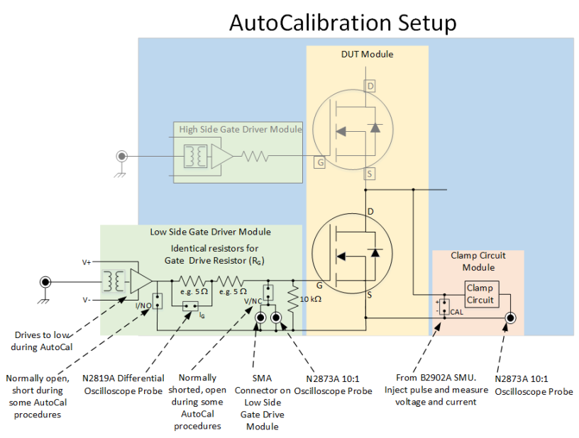
Connecting Probes to the Si/SiC Test Modules
Oscilloscope probes connect to the Test Fixture Modules as follows:
- The DUT Module uses the following oscilloscope probes:
- BNC to SMA cable from the Coaxial Shunt Resistor (ID/IC) to the PD1000-60002 Oscilloscope Protection Probe.
- 10076A High Voltage, 100:1 Probe to the VDS/VCE probe socket.
- The Low Side Gate Driver Module has two oscilloscope probe connections:
- N2873A 10:1 Probe connects to the VGS/VCE probe socket
- N2819A Differential Probe connects to the IG probe socket terminals
- Optionally, if the Clamp Circuit Test Module is used:
- Do not install the N2819A Differential Probe on the IG probe socket terminals of the Low Side Gate Driver Module.
- N2873A 10:1 probe to the VCLAMP socket on the Clamp Module.
IMPORTANT: When installing the N2819A Differential oscilloscope probe on the IG pins on the Low Side Gate Driver Module, the Probe Compensation Adjustment hole must face outward. The Keysight logo must face toward the module. Verify with the +/- symbols on the module and on the probe body.
If you use the Clamp Circuit Module, do not install the N2819A Differential Probe. Instead, install one N2873A 10:1 Oscilloscope Probe connected to the Clamp Test Module (VCLAMP) probe socket.
System Calibration Procedure
To begin the Calibration & Compensation process:
Turn on the PD1500A Test System and allow it to warm-up for at least one hour.
- Install the gate Drive modules that you will use in the Double-Pulse tests. The Gate Drive resistor (RG) is measured calibration and its value stored in an EEPROM on the module.
- Remove the oscilloscope probes from the DPT test fixture and test modules. Do not remove them from the oscilloscope. Probe are re-installed as required for the calibration.
- Select Calibration & Compensation from the Settings drop-down menu.
- Follow all on-screen instructions.
Calibration Requirements
Calibration requires the B2902A/B Precision Source/Measure Unit (SMU) and the following cables/adapters:
- 1251-2277 Banana to BNC Adapter, quantity 1. Used with 2- and 4- wire measurements.
- 8121-2816 BNC to SMA Cable, 1 m, 50 W, quantity 1. Used with 2- and 4- wire measurements.
- 1168B Standard Probe Kit, quantity 1. Used with 2- and 4- wire measurements.
- 2.54 mm jumpers (a package of 10 was provided with the DPT system).
Additional Requirements:
- Perform the Oscilloscope Probe Offset Compensation as the first step in the calibration.
- Unless instructed, both High-Side and Low-Side transistors should be removed from the DUT module (if possible).
- Both High-Side and Low-Side Gate Drive modules, with the same resistance value (RG), are installed on the Test Fixture.
- The Clamp Module is required only for the Clamp Module calibration procedure.
- Perform the oscilloscope probe Deskew as the last calibration step.
All test instruments must be warmed up for at least 60 minutes at ambient temperature before starting the calibration procedure. Failure to allow warm up may result in inaccurate calibration.Initiate Calibration & Compensation Procedures
From the Double-Pulse Test Control tab in the PD1000A Control software, select: Settings > Calibration & Compensation.
Follow all on-screen instructions.
Low Frequency Oscilloscope Probe Offset Compensation
As the first step calibrating the Double-Pulse Test system, the oscilloscope probes must be adjusted for low frequency compensation. For this, the 10076C and N2873A passive probes have built-in compensation RC divider networks. The N2819A Active Differential Probe also requires offset compensation.
Allow the oscilloscope and probe to warm up at ambient temperature for a minimum of 60 minutes (1 hour) before performing the adjustment.Required Equipment
All equipment required for compensation and calibration were provided with the PD1500A test system. This includes:
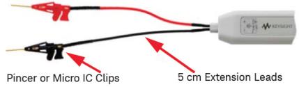
- Spring hook and ground clips for passive oscilloscope probes.
- 5 cm Extension Leads and either Pincer or micro IC clips for the N2819A Differential probe.
- Low Frequency Compensation trimmer/adjustment tools (small plastic screwdriver).
Compensating the 10076C and N2873A Probes
The Infiniium S-Series Oscilloscopes have a square wave reference signal available on the front panel to use for compensating the passive probes. Attach the spring hook and ground clip to the probe and then the square wave reference terminal.
- Refer to the N2873A Probe’s User Guide for instructions. A general description and procedure can also be found on page 5 (Hint #3) of the Keysight 8 Hints for Better Scope Probing.
- Connect the probe to the oscilloscope’s front-panel calibration output (a square wave label is seen near this output).
- Use the supplied trimmer tool to adjust the Low Frequency compensation to an optimum square wave response as shown below.

Adjust so that the square wave on the oscilloscope screen looks square.
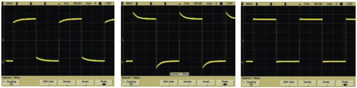
Undercompensated Overcompensated Optimum Due to the 100:1 divider of the 10076C High Voltage Probe, the signal will appear to be very noisy. Therefore, it is beneficial to enable averaging in the Setup > Acquisition menu for suppressing this noise. Setting the number of averages to 16 will result in a clean signal.Compensating the N2819A Differential Probe
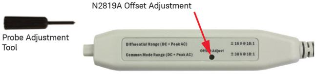
The N2819A Active Differential Probe also requires offset compensation. This is described below and in the N2818/9A Differential Probes User Guide. Use the trimmer tool supplied with the probe to perform the offset zero calibration.
- Connect the probe to an oscilloscope channel input. Turn on the oscilloscope and wait for a minimum of 20 minutes to allow the oscilloscope and probe to warm up.
- Using the probe's 5 cm Extension Leads and the Pincer or Micro IC Clip connection accessories, short the + and - inputs together.
- Press Control > Autoscale on the oscilloscope.
- Press the channel button for the probe and set the oscilloscope channel to DC Coupled mode.
- Set the oscilloscope to Averaging mode (Setup > Acquisition... > Averaging Enabled, x8 or higher) to reduce oscilloscope noise, if needed.
- Set the vertical scale of the oscilloscope to 100 mV/div.
- Using the offset adjustment tool that comes with the probe, adjust the probe offset voltage to zero volts.
In the Compensation & Calibration section of the Control Software, software, click the Skip button when you have completed the probe compensation.
System Calibration Procedure (Autocal) for Si/SiC Devices
Calibration requires the B2902A/B Precision Source/Measure Unit (SMU) and the following cables/adapters:
- 1251-2277 Banana to BNC Adapter, quantity 1. Used with 2- and 4- wire measurements.
- 8121-2816 BNC to SMA Cable, 1 m, 50 W, quantity 1. Used with 2- and 4- wire measurements.
- 1168B Standard Probe Kit, quantity 1. Used with Gate Resistance and the Clamp Module 4-wire calibration measurements.
- 2.54 mm jumpers (a package of 10 was provided with the DPT system).
Requirements
- Perform the Oscilloscope Probe Offset Compensation as the first step in the calibration.
- Unless instructed, both High-Side and Low-Side transistors should be removed from the DUT module (if possible).
- Both High-Side and Low-Side Gate Drive modules, with the same resistance value (RG), are installed on the Test Fixture.
- The PD1000-66505 Clamp Module is required only for the Clamp Module calibration procedure.
- Perform the oscilloscope probe Deskew as the last calibration step.
Gate Voltage Calibration – VGS/VGE Probe
Hardware Setup:
Refer to Figure below.
- Remove the I/NO Jumper on the Low-Side Gate Drive Module.
- Remove the V/NC Jumper on the Low-Side Gate Drive Module.
- Connect the N2873A VGS/VGE Oscilloscope Probe to the Low-Side Gate Drive Module.
- Connect the BNC to Banana Adapter to the BNC to SMA cable.
- Connect the SMA end of the cable to the SMA connector on the Low-Side Gate Drive Module.
- Connect the banana plug cable to Channel 1 Force terminals of the B2902A/B SMU (2-wire measurement).
-
The Safety Enclosure hood may be left open.

Procedure:
After setting up the hardware as described above, click Start to perform the calibration and continue to the Gate Voltage Source Calibration.
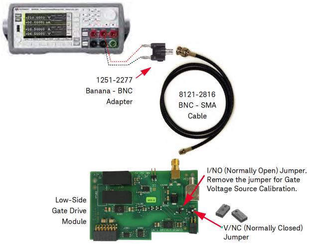
Gate Voltage Source Calibration – VGS Output
Hardware Setup:
Refer to Figure below.
- Remove the I/NO Jumper on the Low-Side Gate Drive Module.
- Install the V/NC Jumper on the Low-Side Gate Drive Module.
- Connect the BNC to Banana Adapter to the BNC to SMA cable.
- Connect the SMA end of the cable to the SMA connector on the Low-Side Gate Drive Module.
- Connect the banana plug cable to Channel 1 Force terminals of the B2902A/B SMU (2-wire measurement)
- The Safety Enclosure hood may be left open.
Procedure:
After setting up the hardware as described above, click Start to perform the calibration and continue to the Gate Current Calibration.
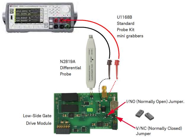
Gate Current Calibration – IG Probe
Hardware Setup:
Refer to Figure above.
- Install the I/NO Jumper on the Low-Side Gate Drive Module.
- Install the V/NC Jumper on the Low-Side Gate Drive Module.
- Connect the N2819A Differential Oscilloscope Probe to the IG pins on the on the Low-Side Gate Drive Module. Carefully observe polarity when installing probe.
-
Connect the U1168B Calibration Cable between the Channel 1 Force terminals of the B2902A/B SMU (2-wire measurement) and the + and - CAL eyelet terminals on the Low-Side Gate Drive Module.
- The Safety Enclosure hood may be left open.
Procedure:
After setting up the hardware as described above, click Start to perform the calibration and continue to the Gate Resistance Calibration.
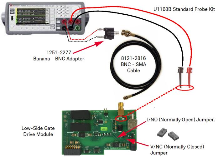
Gate Resistance Calibration – RG
The oscilloscope channel you specify for the Output Current ID/IC in the DPT Control Software Hardware Configuration screen is the channel that the Coaxial Shunt De-embedding is applied to. Refer to the PD1500A Control Software Guide for detailed information.
Hardware Setup:
See Figure below.
- Install the I/NO Jumper on the Low-Side Gate Drive Module.
- Install the V/NC Jumper on the Low-Side Gate Drive Module.
- Refer to Figure below. Install calibration cables to connect the B2902A/B SMU to the Low-Side Gate Drive module for a 4-wire measurement.
- The Safety Enclosure hood may be left open.
Procedure:
After setting up the hardware as described above, click Start to perform the calibration and continue to the High Voltage Probe Calibration.
High Voltage Probe Calibration – VDS/VCE Probe
Hardware Setup:
- Install a High-Side Gate Drive Module (0 W Gate Resistor)
- Install a 1200 V FET (for example, the SCT2080KE FET supplied with the PD1500A) in the High-Side position of the DUT module.
- Remove any FET in the Low-Side position of the DUT Module.
- Remove (do not install) the Low-Side Gate Drive Module.
- Connect the 10076C High Voltage Probe to the DUT Module.
-
Remove all other cables and oscilloscope probes.

Procedure
After setting up the hardware as described above, click Start to perform the calibration and continue to the Clamp Circuit Probe Calibration.
Clamp Circuit Probe Calibration – VCLAMP Probe
Hardware Setup:
See Figure below.

Procedure:
After setting up the hardware as described above, click Start to perform the calibration and then continue to the next step.
PD1000-60002 Protection Probe Calibration – ID/IC
Hardware Setup:
Refer to Figure below.
- Connect the PD1000-60002 Protection Probe to the Oscilloscope.
- Connect the BNC to Banana Adapter to the BNC to SMA cable.
- Connect the SMA end of the cable to the SMA connector on the PD1000-60002 Protection Probe. Use the 0.56 N-m (5 lb-in) 5/16 in. SMA Break-over torque wrench (provided with the PD1500A system) to tighten the cable to the PD1000-60002 Protection Probe.
- Connect the banana plug cable to Channel 1 Force terminals of the B2902A SMU (2-wire measurement).
- The Safety Enclosure hood may be left open for this calibration step.

Procedure:
After setting up the hardware as described above, click Start to perform the calibration and then continue to the next step.
Coaxial Shunt Resistor
There is no separate calibration for the PD1000-61901 Coaxial Shunt Resistor. The De-embedding file installed in the DSOS104 Oscilloscope provides the necessary accuracy. See Coaxial Shunt Resistor and De-Embedding File.
Oscilloscope Probe Deskew
A small propagation delay difference exists between different types of oscilloscope probes (e.g., voltage vs. current probes). Although this difference is small, it is significant and is caused by each probe’s unique internal circuitry and cable length. This propagation delay difference is known as “skew” and creates an error when calculating switching loss or measuring timing. In general, the outcome is that all probes must be aligned!
Deskew is a process of applying a signal from the Waveform Generator to all four oscilloscope channels simultaneously. The PD1000A Control Software measures the time difference between channels relative to oscilloscope Channel 3. Finally, the oscilloscope automatically calculates and sets the channel-to-channel skew factor.
After the Oscilloscope Probe Compensation and System Calibration, the last step is to run Deskew. Deskew has the greatest impact on both On and Off Delay times and hence affects the total Switching Time. Both On and Off Switching Energies are also affected.
The following table lists the required alignment for the different measurements.
| Parameter | Required Alignment |
|---|---|
| Turn on delay td(on | ) VGS, VDS |
| Turn on rise time tr | None |
| Turn on Energy e(on) | VGS, VDS, ID |
| Turn off delay td(off) | VGS, VDS |
| Turn off fall time tf | None |
| Turn off Energy e(off) | VGS, VDS, ID |
| Reverse Recovery Time trr | None |
| Reverse Recovery Charge Qrr | None |
| Reverse Recovery Energy Err of Diode | VDS, ID |
| Gate Charge QGS, QGD, QG | VGS, IG |
| RDS(on) | VDS (clamped), ID |
| IV-Curve | VGS, IG |
Connect Probes to Deskew Fixture
After the Oscilloscope Probe Compensation and System Calibration, the last step is to run Deskew.
Hardware Setup
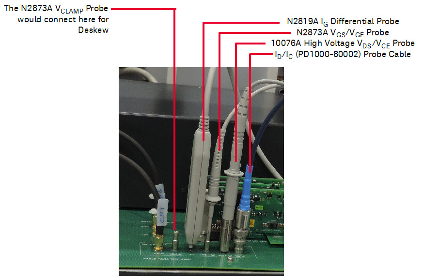
Because the oscilloscope has only four input channels and the DPT test fixture uses only four oscilloscope probes at a time, then only four probes may be deskewed at one time. Typically, either the N2819A Differential Probe (for measuring IG) or the N2873A (VCLAMP) probe are used in a DPT test; rarely are they both used at the same time. Deskew the probes that you will be using in your test. Figure below shows the typical configuration for Deskewing the oscilloscope probes.
- Locate the Deskew oscilloscope probe connectors on the main Test Fixture. See figure below.
- Remove the SMA cable from the Low Side SMA connector on the Test Fixture and connect it to the Cal (Deskew) Input SMA connector.
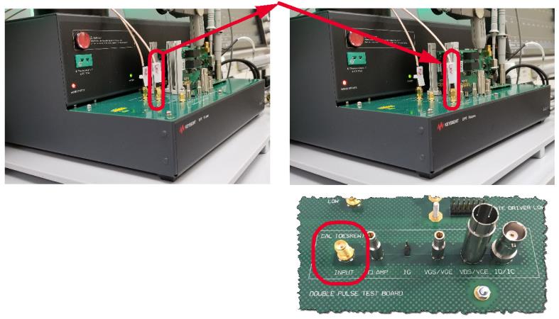
The BNC connector (ID/IC) on the far right is for the PD1000-60002 Oscilloscope Protection probe cable that would normally connect to the Coaxial Shunt Resistor on the DUT Test Module.
- Connect the oscilloscope probes to the Deskew section of the Test Fixture.
Procedure:
- After setting up the oscilloscope probes in the Deskew fixture, click Start to perform Deskew calibration.
- When complete, return the oscilloscope probes to the appropriate connectors on the DUT and Test Modules.
- Return the SMA cable from the Cal (Deskew) Input SMA connector to the Low Side SMA connector on the Test Fixture.
This concludes the Compensation and Calibration procedure.